- Posts: 33
- Karma: 1
- Thank you received: 6
Forum Login
iMac efi
Rendering Error in layout Widget/Social: Call to a member function exists() on null. Please enable debug mode for more information.
7 years 11 months ago #3148 by ggltech
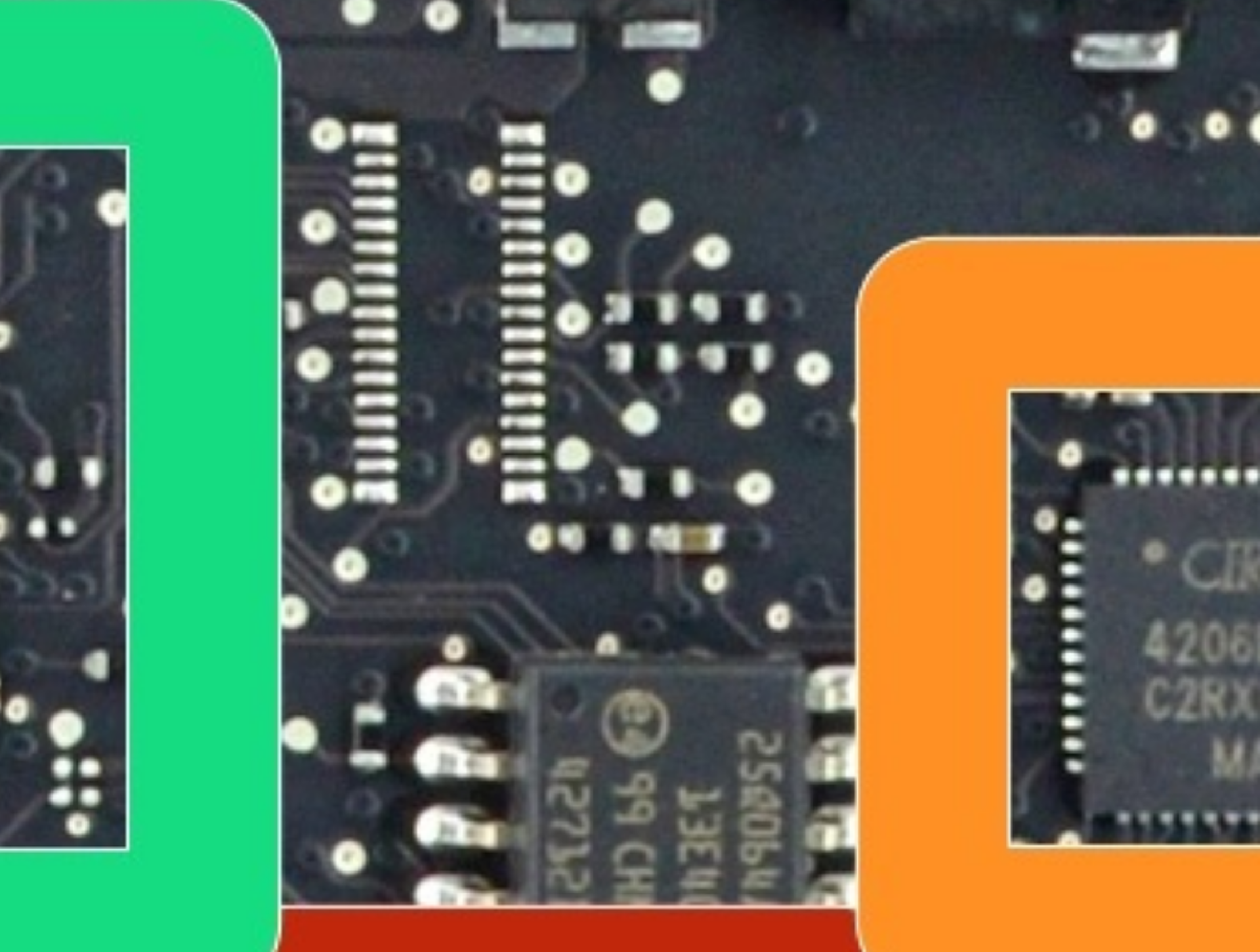
Can someone who has one of these logic boards matchup all 8 legs of the SOP chip to the pads beside the missing programming port ?
ggltech wrote:
thaGH05T wrote: It is a QFN fast.flow, but still sucks. i think there have to be a group of pads or a port that connects to it because apple has to do ISP and tests. If for some odd reason there is not I can assume that we could look for an alternate custom solution with a 3d printed clip.
They are not to bad to solder..but i don't see any available for purchase preprogrammed on ebay.
The picture attached shows a 2015 model with a SOP 8-Pin BIOS but think they have changed it to a 8 pin QFN...if you look above it programming port solder pads with missing port. ?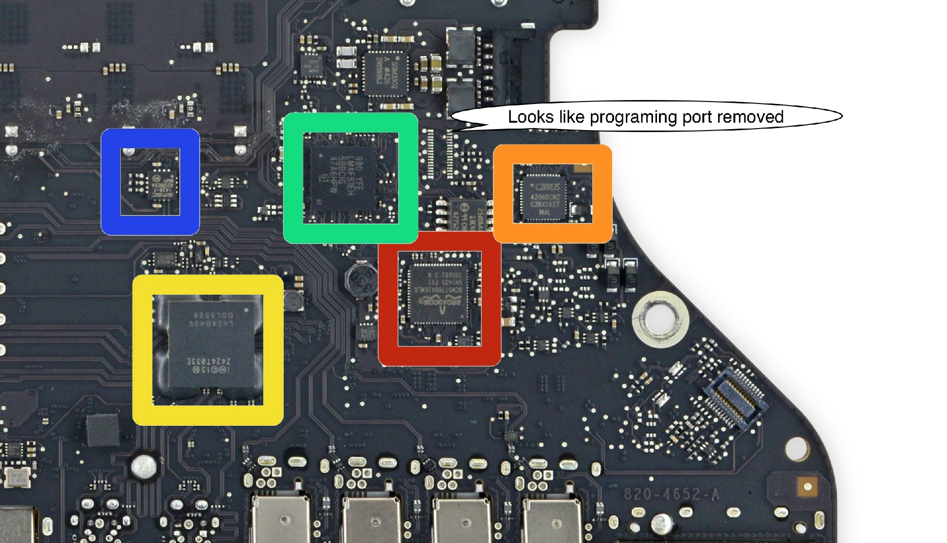
Can someone who has one of these logic boards matchup all 8 legs of the SOP chip to the pads beside the missing programming port ?
Please Log in or Create an account to join the conversation.
- rubberbudgie
-

- Offline
- Noob
-

Less More
- Posts: 7
- Karma: 1
- Thank you received: 0
7 years 10 months ago #3255 by rubberbudgie
Replied by rubberbudgie on topic iMac efi
I'm currently working on one of these (5K late 2015) and have traced out the corresponding test points on the board for all of the pins to the EFI flash chip apart from the VCC which makes sense being power. If you guys don't have them already I'm happy to post them here.
I have soldered wires onto the test points and connected it to the RPI and the logic board has a green LED lit up but flashrom cannot see the chip. I'm guessing it's got to do with where/how I am supplying power to the chip, I might have to bite the bullet and solder a wire directly onto the VCC pin (which I'd rather not do if I can avoid it seeing as getting the wires onto the test points was bad enough without a decent magnifier).
So seeing as there isn't a test point for the VCC pin, can anyone suggest a good spot to supply power to the chip or am I going to have to connect directly to it?
Please Log in or Create an account to join the conversation.
7 years 10 months ago #3257 by thaGH05T
If I helped you, buy me a beer!!! Happy Hunting...
I have not laid eyes on a 5k, but I would look at the trace and see if it leads back to a larger component you may be able to solder to.
If I helped you, buy me a beer!!! Happy Hunting...
Please Log in or Create an account to join the conversation.
- rubberbudgie
-
- Offline
- Noob
-
Less More
- Posts: 7
- Karma: 1
- Thank you received: 0
7 years 10 months ago #3258 by rubberbudgie
I've attached a wire to a capacitor that is next to the chip that has continuity with pin 8 (VCC) so hopefully that should do the trick. I'm going through and shortening all of my wires between the board and the RPI as too long wires caused me problems with the MBA.
Think I might order an infrared rework station as it is looking more and more likely that they will be using BGA type chips and not putting header sockets on the boards as this is the second MAC I've encountered in as many days without a header or easily accessible firmware chip
Replied by rubberbudgie on topic iMac efi
thaGH05T wrote: I have not laid eyes on a 5k, but I would look at the trace and see if it leads back to a larger component you may be able to solder to.
I've attached a wire to a capacitor that is next to the chip that has continuity with pin 8 (VCC) so hopefully that should do the trick. I'm going through and shortening all of my wires between the board and the RPI as too long wires caused me problems with the MBA.
Think I might order an infrared rework station as it is looking more and more likely that they will be using BGA type chips and not putting header sockets on the boards as this is the second MAC I've encountered in as many days without a header or easily accessible firmware chip
Please Log in or Create an account to join the conversation.
7 years 10 months ago #3259 by thaGH05T
If I helped you, buy me a beer!!! Happy Hunting...
Man, there absolutely has to be a way they interface with it. Apple programs them in circuit!
If I helped you, buy me a beer!!! Happy Hunting...
Please Log in or Create an account to join the conversation.
- rubberbudgie
-
- Offline
- Noob
-
Less More
- Posts: 7
- Karma: 1
- Thank you received: 0
7 years 10 months ago #3260 by rubberbudgie
Replied by rubberbudgie on topic iMac efi
Unless they are pre-programmed before being installed at the factory and then updates etc are programmed by software (ie with the MAC equivalent of Winflash) like most mainboard manufacturers do. That would explain why Apple are so worried about Thunderstrike etc. Might be worth investing some time seeing if a modified version of TS would work as a "flashing tool" and do a whole ROM rather than just injecting small pieces of code.....
Please Log in or Create an account to join the conversation.
7 years 10 months ago #3261 by thaGH05T
If I helped you, buy me a beer!!! Happy Hunting...
If you have the knowledge of creating and hooking efi programs and loading them as an option ROM go ahead ") I cannot do that yet. AFAIK they have always done ISP when it comes to a few chips. They may have changed that up though. Also, please do post the test point pinout etc.
I cannot do that yet. AFAIK they have always done ISP when it comes to a few chips. They may have changed that up though. Also, please do post the test point pinout etc.
If I helped you, buy me a beer!!! Happy Hunting...
Please Log in or Create an account to join the conversation.
- rubberbudgie
-
- Offline
- Noob
-
Less More
- Posts: 7
- Karma: 1
- Thank you received: 0
7 years 10 months ago #3262 by rubberbudgie
I'm having problems getting flashrom to recognize the bios chip so I'm not 100% sure that the test points are correct but once I have it working I will definitely post the relevant info. I just tried hooking the WP and HOLD pins up to the VCC but still no luck. I have checked and double-checked the connections and everything "seems" OK. Might have to remove the chip altogether. I vaguely recall reading somewhere that the chip does need to be removed, will keep you posted anyway.
Replied by rubberbudgie on topic iMac efi
thaGH05T wrote: If you have the knowledge of creating and hooking efi programs and loading them as an option ROM go ahead
I'm having problems getting flashrom to recognize the bios chip so I'm not 100% sure that the test points are correct but once I have it working I will definitely post the relevant info. I just tried hooking the WP and HOLD pins up to the VCC but still no luck. I have checked and double-checked the connections and everything "seems" OK. Might have to remove the chip altogether. I vaguely recall reading somewhere that the chip does need to be removed, will keep you posted anyway.
Please Log in or Create an account to join the conversation.
7 years 10 months ago #3263 by thaGH05T
If I helped you, buy me a beer!!! Happy Hunting...
Thanks man, looking forward to it.
If I helped you, buy me a beer!!! Happy Hunting...
Please Log in or Create an account to join the conversation.
- rubberbudgie
-
- Offline
- Noob
-
Less More
- Posts: 7
- Karma: 1
- Thank you received: 0
7 years 10 months ago #3303 by rubberbudgie
Replied by rubberbudgie on topic iMac efi
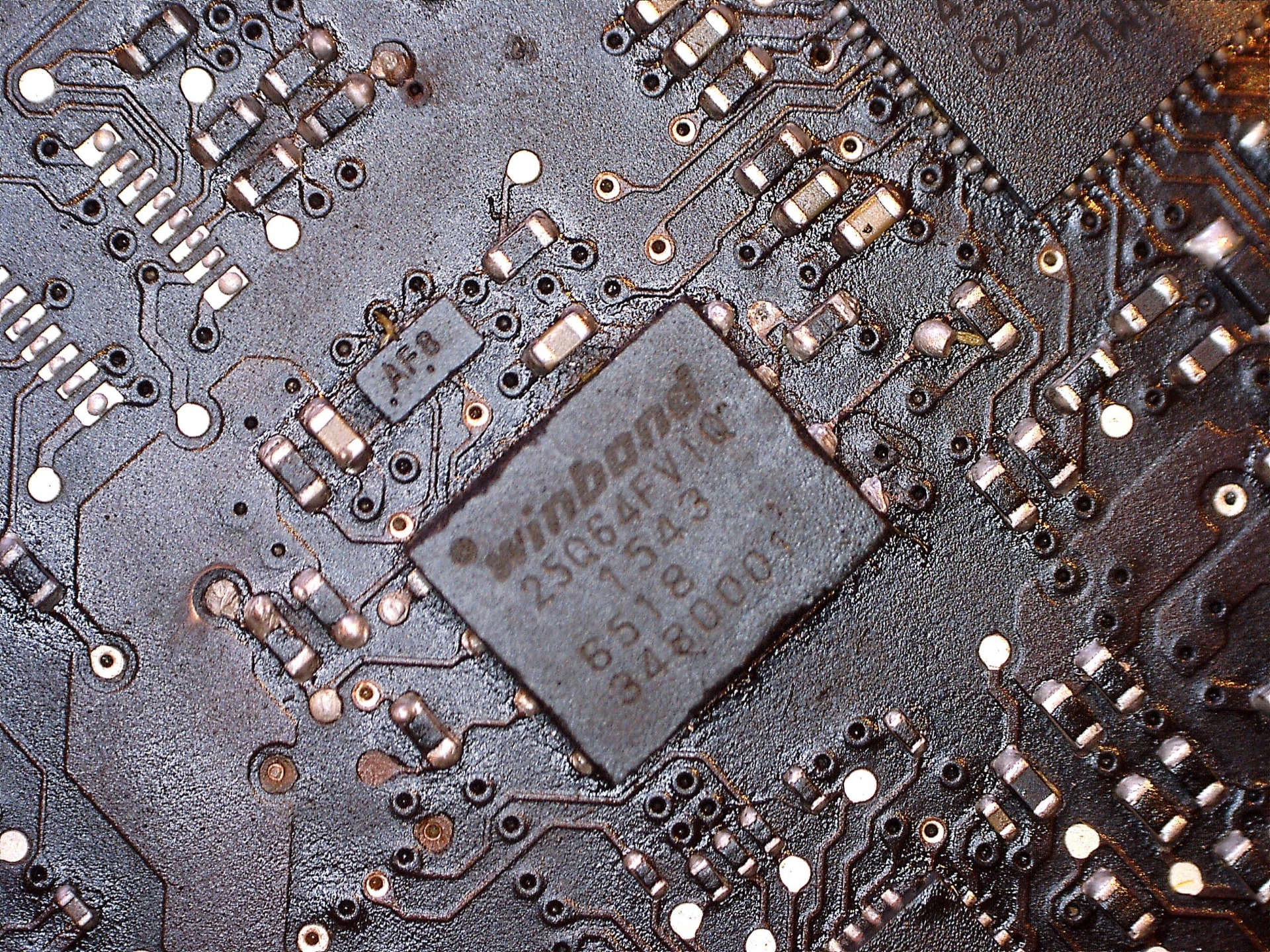
Sorry for the delay in getting back to you, decided to jump in head first and buy a bunch of equipment to try and get this board sorted. Ended up with a hot-air station, USB microscope and the usual SMD stuff (tweezers, flux, paste etc) but still no luck getting the QFN chip off the board. I'm guessing the center ground pad is soldered on and must be connected through to the ground-plane most likely as the board seems to be soaking up the heat stopping the solder from melting. It quite possibly could also be glued onto the board as an added fuck-you from Apple but I can't say for sure. I don't want to give it any more heat than I already have as it must be close to if not already fucked from all of the heat it has copped so far.
If anyone has had any experience getting these off I'd certainly welcome any suggestions.
In the meantime I have attached a close-up image of the chip and the surrounding test-points. The VCC traces back to the cap above the Winbond logo.
If anyone has had any experience getting these off I'd certainly welcome any suggestions.
In the meantime I have attached a close-up image of the chip and the surrounding test-points. The VCC traces back to the cap above the Winbond logo.
Please Log in or Create an account to join the conversation.
7 years 10 months ago #3304 by ggltech
Should be easy .
Hold your hot air gun about 2-3 inches away from the board ..in circular motion gradually use it to warm the board up around the chip..should take about 1min.
Now move closer 1/2 inch and apply heat only to chip.. Warning : make sure you are not blowing to much air or small components will blow away !
Use tweezers and touch it to see if it moves ..and lift off.
sometimes I add flux just before the lift.
Good luck !
Please Log in or Create an account to join the conversation.
7 years 10 months ago #3317 by thaGH05T
If I helped you, buy me a beer!!! Happy Hunting...
Yea there is a lot of damage so be very careful with the airflow...
If I helped you, buy me a beer!!! Happy Hunting...
Please Log in or Create an account to join the conversation.
- rubberbudgie
-
- Offline
- Noob
-
Less More
- Posts: 7
- Karma: 1
- Thank you received: 0
7 years 10 months ago #3318 by rubberbudgie
Tried that but doesn't matter how much heat is applied to the chip it just won't move. The solder on the side pins is molten as are all the components around it but the heat just isn't getting to the center ground pad, or possibly the chip is glued down as I can see what looks like some sort of adhesive between the board and the chip.
I double-checked on a test board just to make sure the new hot-air station was working correctly and temp readings were accurate and worked perfectly on everything I tried including BGA's (which I've always avoided in the past). I even tried a few QFN's and they came off no problems at all which is why I'm thinking there is something else at work here.
I've accepted that I've most likely fried this chip so I will order a few replacements which is no issue but I still need to get this bloody thing off either way.
Replied by rubberbudgie on topic iMac efi
ggltech wrote: Should be easy .
Hold your hot air gun about 2-3 inches away from the board ..in circular motion gradually use it to warm the board up around the chip..should take about 1min.
Now move closer 1/2 inch and apply heat only to chip.. Warning : make sure you are not blowing to much air or small components will blow away !
Use tweezers and touch it to see if it moves ..and lift off.
sometimes I add flux just before the lift.
Good luck !
Tried that but doesn't matter how much heat is applied to the chip it just won't move. The solder on the side pins is molten as are all the components around it but the heat just isn't getting to the center ground pad, or possibly the chip is glued down as I can see what looks like some sort of adhesive between the board and the chip.
I double-checked on a test board just to make sure the new hot-air station was working correctly and temp readings were accurate and worked perfectly on everything I tried including BGA's (which I've always avoided in the past). I even tried a few QFN's and they came off no problems at all which is why I'm thinking there is something else at work here.
I've accepted that I've most likely fried this chip so I will order a few replacements which is no issue but I still need to get this bloody thing off either way.
Please Log in or Create an account to join the conversation.
- reverendalc
-

- Offline
- Haxor God
-

- This isn't Monaco... This is Baghdad
Less More
- Posts: 760
- Karma: 23
- Thank you received: 137
7 years 5 months ago #5302 by reverendalc
Replied by reverendalc on topic iMac efi
did this ever get sorted? i have a late 2015 4k in my hands, and i'm anxious to crack it open
Please Log in or Create an account to join the conversation.
7 years 5 months ago #5303 by thaGH05T
If I helped you, buy me a beer!!! Happy Hunting...
What do you mean rev?
If I helped you, buy me a beer!!! Happy Hunting...
Please Log in or Create an account to join the conversation.
- reverendalc
-
- Offline
- Haxor God
-
- This isn't Monaco... This is Baghdad
Less More
- Posts: 760
- Karma: 23
- Thank you received: 137
7 years 5 months ago #5305 by reverendalc
Replied by reverendalc on topic iMac efi
did anybody successfully interface with the chip in circuit?
Please Log in or Create an account to join the conversation.
- reverendalc
-
- Offline
- Haxor God
-
- This isn't Monaco... This is Baghdad
Less More
- Posts: 760
- Karma: 23
- Thank you received: 137
7 years 5 months ago #5307 by reverendalc
Replied by reverendalc on topic iMac efi
yes i've got an 852++ and i'm handy with the shit, and i've even got replacement chips in hand...
but there has GOT to be a way to flash the chip in place. i can't imagine apple writing firmware chip by chip
but there has GOT to be a way to flash the chip in place. i can't imagine apple writing firmware chip by chip
Please Log in or Create an account to join the conversation.
- reverendalc
-
- Offline
- Haxor God
-
- This isn't Monaco... This is Baghdad
Less More
- Posts: 760
- Karma: 23
- Thank you received: 137
7 years 5 months ago - 7 years 5 months ago #5308 by reverendalc
Replied by reverendalc on topic iMac efi
yes i've got an 852++ and i'm handy with the shit, and i've even got replacement chips in hand...
but there has GOT to be a way to flash the chip in place. i can't imagine apple writing firmware chip by chip
i've pulled the board. the spot where it looks like a debug header would be... there is no continuity between any leg of the EFI chip nor any pad on the grouping.
but there has GOT to be a way to flash the chip in place. i can't imagine apple writing firmware chip by chip
i've pulled the board. the spot where it looks like a debug header would be... there is no continuity between any leg of the EFI chip nor any pad on the grouping.
Last edit: 7 years 5 months ago by reverendalc.
Please Log in or Create an account to join the conversation.
Who's Online
We have 143 guests and no members online
N00BZ
- ljamal
- ljamal74
- mikeg2atest
- ducchinhbui
- anjarezt
Cookies
EU e-Privacy Directive
This website uses cookies to manage authentication, navigation, and other functions. By using our website, you agree that we can place these types of cookies on your device.
You have declined cookies. This decision can be reversed.
You have allowed cookies to be placed on your computer. This decision can be reversed.