
- Posts: 9
- Thank you received: 0
Forum Login
Dumping eeprom using EZP eeprom reader
Rendering Error in layout Widget/Social: Call to a member function exists() on null. Please enable debug mode for more information.
7 years 7 months ago #4353 by Jastr
Dumping eeprom using EZP eeprom reader was created by Jastr
I'm trying to dump efi from new MacBook. Can anyone help me creating correct diagram i will photo document and create pdf for forum.
How about dip switch on service connector?


How about dip switch on service connector?
Please Log in or Create an account to join the conversation.
7 years 7 months ago #4358 by k-pax
Replied by k-pax on topic Dumping eeprom using EZP eeprom reader
beautiful pictures
Please Log in or Create an account to join the conversation.
7 years 7 months ago #4361 by Jastr
Replied by Jastr on topic Dumping eeprom using EZP eeprom reader
What's wrong with the pictures?
Please Log in or Create an account to join the conversation.
7 years 7 months ago #4398 by Jastr
Replied by Jastr on topic Dumping eeprom using EZP eeprom reader
No one knows what eeprom is on the MB?
Please Log in or Create an account to join the conversation.
- reverendalc
-

- Offline
- Haxor God
-

- This isn't Monaco... This is Baghdad
Less More
- Posts: 760
- Karma: 23
- Thank you received: 137
7 years 7 months ago #4400 by reverendalc
Replied by reverendalc on topic Dumping eeprom using EZP eeprom reader
your MacBook should have a macronix MX25L6406E chip.
this pinout is:
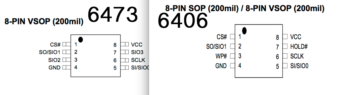
that is chip on pcb. if you're interfacing your programmer with the clip onto the debug header...
are you asking for the pinout of the debug clip?
also, verify your 3.3v amperage from that programmer. if it's not ~2A, you may need to replace VCC and GND with a 3.3v battery
this pinout is:
that is chip on pcb. if you're interfacing your programmer with the clip onto the debug header...
are you asking for the pinout of the debug clip?
also, verify your 3.3v amperage from that programmer. if it's not ~2A, you may need to replace VCC and GND with a 3.3v battery
Please Log in or Create an account to join the conversation.
7 years 7 months ago #4410 by Jastr
Replied by Jastr on topic Dumping eeprom using EZP eeprom reader
Ok i'll try to messure it! But with that chip i get no data. And the ezp is the programmer of a lot of the other tool kits around so guess it should be able to read it?
Please Log in or Create an account to join the conversation.
- therealjayvi
-

- Offline
- Admin
-

- Wherever you go, there you are
7 years 7 months ago #4467 by therealjayvi
Replied by therealjayvi on topic Dumping eeprom using EZP eeprom reader
I've never heard of the EZP but I have used a similar looking device called SOFI programmer and it uses a similar interface and device setup. Using the SOFI I was unsuccessful it using it for any type of ISP operations. The only success I had with it was after physically removing the chip and flashing it externally which is honestly more work than is needed. I cannot say anything about the EZP flasher but if it's anything like a majority of the other flash devices I've used before finally buying a Pi then it will not be able to pull a read because there is a voltage drop on the VCC pin. In your second picture if you look at the right side of your connector you will see two holes for VCC and GND that are unused. The developers of these devices know about the specifications needed with ISP devices and give you the option to add additional voltage directly into your VCC line from the nearest possible point. If you wish to have any luck using this device then my advice is to solder two pin heads into those spots and connect a 3.3v line into it. Most Vape pens take 3.3v batteries to operate so if u have any or know anybody who does then that is a perfect use for the battery. Just connect lines from the battery ends into those two spots on the connector I mentioned and give it a try. Honestly though we all advise using the Pi not just to be particular to it but because it is efficient and has many other uses besides using it as an SPI device. Also try different combinations of battery/MagSafe plugged in or not as this makes all the difference in certain models. Best of luck, let us know your results!
Sent from my iPhone using Tapatalk
Sent from my iPhone using Tapatalk
Please Log in or Create an account to join the conversation.
- reverendalc
-
- Offline
- Haxor God
-
- This isn't Monaco... This is Baghdad
Less More
- Posts: 760
- Karma: 23
- Thank you received: 137
7 years 7 months ago #4474 by reverendalc
Replied by reverendalc on topic Dumping eeprom using EZP eeprom reader
you'll definitely need to have at least 3.3V2A power to program the chip in-circuit.
your programmer will work fine if you pull the chip.
your programmer will work fine if you pull the chip.
The following user(s) said Thank You: CygnusX1
Please Log in or Create an account to join the conversation.
7 years 7 months ago - 7 years 7 months ago #4481 by modemer
Replied by modemer on topic Dumping eeprom using EZP eeprom reader
You don't need to lift the chip. If you have the tools and knowledge needed to lift it, then you have the tools and skills needed to simply solder to it.
If you do not want to solder, you can just buy some "single pin grabber clips" Which is what I used and an spi programmer called; usbjtagNT.
Its the fastest programmer in its price range and has an absolutely beautiful and incredibly easy to use gui.
OR..If you dont want to spend the 60$ for this tool, you can just whip together/build an LPT spi reader/writer. However, the read/write times will be roughly 10-20 min each way, but its free and will do the trick.
These are the exact clips that I used (roughly $1.50):

Grab some dupont cables too, then attach them to the clips. You can then slide the other end of the dupont cable onto the pin(s) of your reader/writer.
If you do not want to solder, you can just buy some "single pin grabber clips" Which is what I used and an spi programmer called; usbjtagNT.
Its the fastest programmer in its price range and has an absolutely beautiful and incredibly easy to use gui.
OR..If you dont want to spend the 60$ for this tool, you can just whip together/build an LPT spi reader/writer. However, the read/write times will be roughly 10-20 min each way, but its free and will do the trick.
These are the exact clips that I used (roughly $1.50):
Grab some dupont cables too, then attach them to the clips. You can then slide the other end of the dupont cable onto the pin(s) of your reader/writer.
Last edit: 7 years 7 months ago by modemer.
Please Log in or Create an account to join the conversation.
- reverendalc
-
- Offline
- Haxor God
-
- This isn't Monaco... This is Baghdad
Less More
- Posts: 760
- Karma: 23
- Thank you received: 137
7 years 7 months ago #4482 by reverendalc
Replied by reverendalc on topic Dumping eeprom using EZP eeprom reader
That's a novel idea for SOP8 chips, and not a new idea. We are however dealing with TSSOP chips which have no exposed legs to clip onto.
There are nearby pads which can be soldered onto, but that doesn't change the facts: when the chip is in circuit, other components will attempt to power up. If your programmer isn't high enough amperage, it will still be insufficient for programming in circuit.
There are nearby pads which can be soldered onto, but that doesn't change the facts: when the chip is in circuit, other components will attempt to power up. If your programmer isn't high enough amperage, it will still be insufficient for programming in circuit.
Please Log in or Create an account to join the conversation.
Who's Online
We have 518 guests and no members online
N00BZ
- ljamal
- ljamal74
- mikeg2atest
- ducchinhbui
- anjarezt
Cookies
EU e-Privacy Directive
This website uses cookies to manage authentication, navigation, and other functions. By using our website, you agree that we can place these types of cookies on your device.
You have declined cookies. This decision can be reversed.
You have allowed cookies to be placed on your computer. This decision can be reversed.