- Posts: 11
- Thank you received: 0
Forum Login
MacBook 12 A1534 EMC 2991
Rendering Error in layout Widget/Social: Call to a member function exists() on null. Please enable debug mode for more information.
7 years 3 months ago #6006 by perarg
MacBook 12 A1534 EMC 2991 was created by perarg
Hello to all of you,
i found the forum yestreday while i am searching a way to reset the EFI from my macbook. I spent many many hours of reading and watching youtube guides, everything from ghostlyhaks.com. To be honest i am confused right now.
I don't know where to start, please somebody light my way
I have to tell you that i have a raspberry pi so i can make everything needed concerned to the raspberry part. But i don't know what to do with the chipset.
Member @ChomsMaster has successfully reset EFI as shown at the following post here . But his macbook is EMC 2746... maybe a lot of things have changed in newest models as mine... (He was soldering the pins and not using a clip)
Here is another question for EMC 2991 about the chip. @mariob indicates the chipset place. @reverendalc shows the possible pin arrangement. @Ghost3DO used another pinout as he posted here . But he said that he can read and not write.
Excuse my ignorance but i am confused about on what chipset to work. Do i need 3.3v or 1.8v ? Do i need a clip or i can try soldering ? What are the right pins from chipset to raspberry pi ?
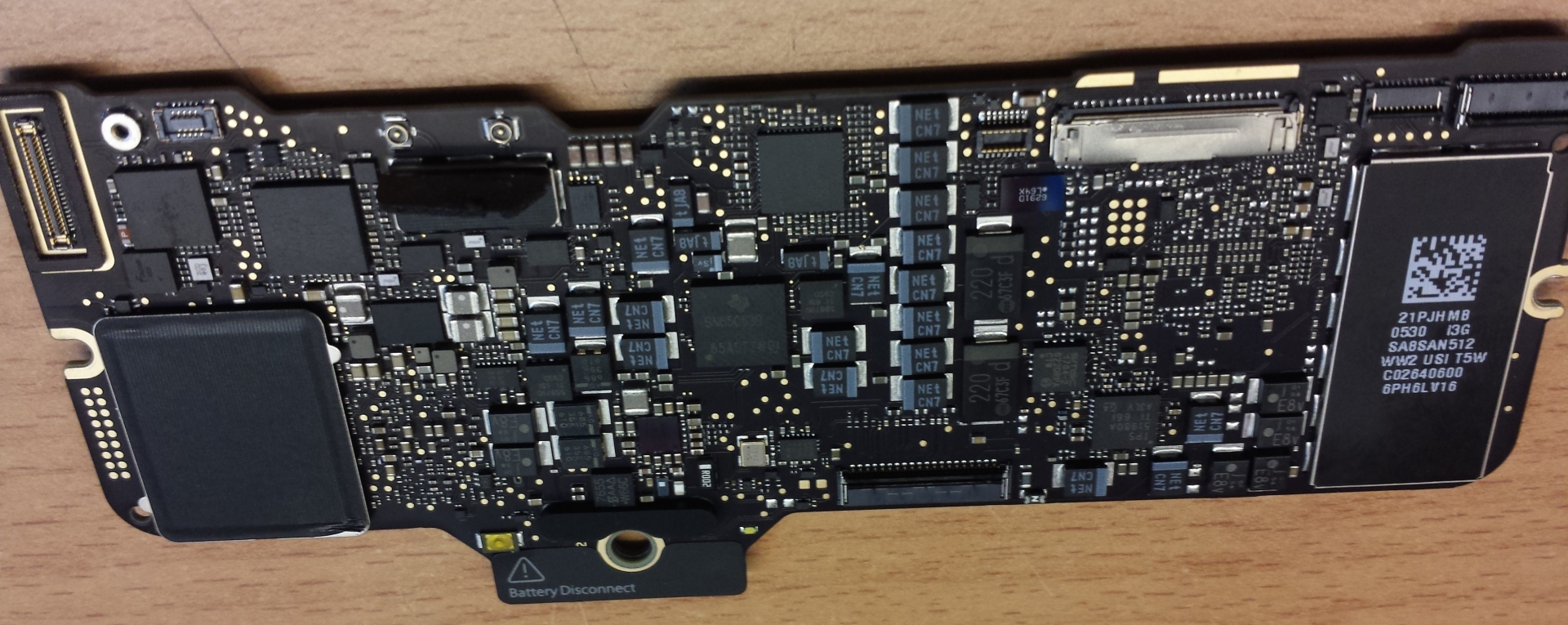
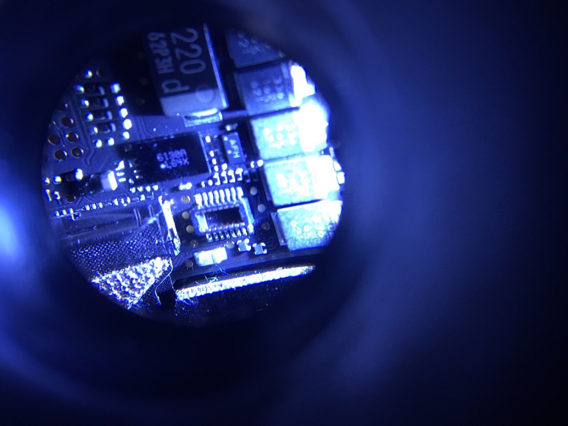
I attached a photo of my macbook board...
I hope everybody has a happy new year!
i found the forum yestreday while i am searching a way to reset the EFI from my macbook. I spent many many hours of reading and watching youtube guides, everything from ghostlyhaks.com. To be honest i am confused right now.
I don't know where to start, please somebody light my way
I have to tell you that i have a raspberry pi so i can make everything needed concerned to the raspberry part. But i don't know what to do with the chipset.
Member @ChomsMaster has successfully reset EFI as shown at the following post here . But his macbook is EMC 2746... maybe a lot of things have changed in newest models as mine... (He was soldering the pins and not using a clip)
Here is another question for EMC 2991 about the chip. @mariob indicates the chipset place. @reverendalc shows the possible pin arrangement. @Ghost3DO used another pinout as he posted here . But he said that he can read and not write.
Excuse my ignorance but i am confused about on what chipset to work. Do i need 3.3v or 1.8v ? Do i need a clip or i can try soldering ? What are the right pins from chipset to raspberry pi ?
I attached a photo of my macbook board...
I hope everybody has a happy new year!
Please Log in or Create an account to join the conversation.
- reverendalc
-

- Offline
- Haxor God
-

- This isn't Monaco... This is Baghdad
Less More
- Posts: 760
- Karma: 23
- Thank you received: 137
7 years 3 months ago #6007 by reverendalc
Replied by reverendalc on topic MacBook 12 A1534 EMC 2991
you can use an adapter clip, or you can connect wires yourself.
instead of soldering directly to board, try soldering wires to sewing needles, and using temporary adhesive to hold sewing needles in contact with EFI chip.
there are TWO SPI ROMS available via the debug header. there was some confusion. thanks to mariob, it is clear:
the SSDROM is 1.8v
the EFIROM is 3.3v
reading (and not being able to write) is due to WREN not being set. it's currently not possible to set WREN with raspberry pi, so you'll have to find a power state of the MacBook where the chip is powered, WREN is set, and the chip is not locked by another transaction
The following user(s) said Thank You: perarg
Please Log in or Create an account to join the conversation.
- ChomsMaster
-

- Offline
- Script Kiddy
-

Less More
- Posts: 33
- Karma: 6
- Thank you received: 17
7 years 3 months ago #6024 by ChomsMaster
Replied by ChomsMaster on topic MacBook 12 A1534 EMC 2991
Hello everyone,
Forgive my English, it is very bad, but I will try to explain what the connections in EMC 2991 would be.
For example:
Compare the scheme of a retina 13 with MacBook 12, result:
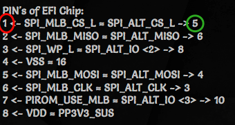
PIN's of EFI Chip:
1 <- SPI_MLB_CS_L = SPI_ALT_CS_L -> 5
2 <- SPI_MLB_MISO = SPI_ALT_MISO -> 6
3 <- SPI_WP_L = SPI_ALT_IO <2> -> 8
4 <- VSS = 16
5 <- SPI_MLB_MOSI = SPI_ALT_MOSI -> 4
6 <- SPI_MLB_CLK = SPI_ALT_CLK -> 3
7 <- PIROM_USE_MLB = SPI_ALT_IO <3> -> 10
8 <- VDD = PP3V3_SUS
For more details see pictures,
Best Regards,
Oscar Salcedo
Forgive my English, it is very bad, but I will try to explain what the connections in EMC 2991 would be.
For example:
Compare the scheme of a retina 13 with MacBook 12, result:
PIN's of EFI Chip:
1 <- SPI_MLB_CS_L = SPI_ALT_CS_L -> 5
2 <- SPI_MLB_MISO = SPI_ALT_MISO -> 6
3 <- SPI_WP_L = SPI_ALT_IO <2> -> 8
4 <- VSS = 16
5 <- SPI_MLB_MOSI = SPI_ALT_MOSI -> 4
6 <- SPI_MLB_CLK = SPI_ALT_CLK -> 3
7 <- PIROM_USE_MLB = SPI_ALT_IO <3> -> 10
8 <- VDD = PP3V3_SUS
For more details see pictures,
Best Regards,
Oscar Salcedo
The following user(s) said Thank You: reverendalc, perarg
Please Log in or Create an account to join the conversation.
7 years 3 months ago - 7 years 3 months ago #6039 by perarg
Replied by perarg on topic MacBook 12 A1534 EMC 2991
reverendalc: Thank you for your info. If i should buy clip from ghostlyhaks, can you give me the link to the right product i have to use ? Where i will "clip" it ? The issue with WREN may be so serious so finally i will never achieve to unlock the EFI or always there is a way to make it works ? Your way with clipping the chipset is combined with ChomsMaster's way below or his way is another alternative ?
ChomsMaster: English is not my mother language, so don't be anxious on it. At least for me, everything is ok. Thank you for your tryings to help. You post a lot of images showing us the pins to be soldered (?) As i show you in following image, i cannot understand what is in the red circle and what is in the green ? Can you be more specific ? There is one chance that i have understand... These are the 8 pins that i have to connect to the raspberry pi ?
Let's take an example of one of your images. The following image is Picture7.png.
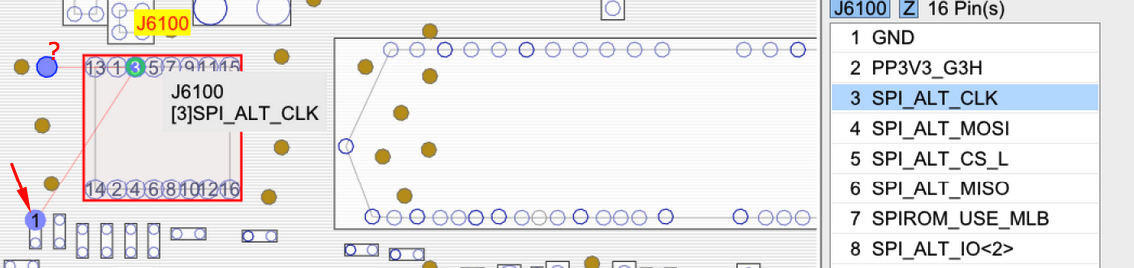
This is the 6th pin ? I have to solder the pin with red arrow ?? And what is the other pin (the one with the question mark ?).
So when i have connected all the 8 pins, the other end of wires will be connected to the Raspberry pi ? And then following the process from the tutorials ? (Read the firmware, change the lock password by replacing the hex code and then write back to the chipset ?) Do you have the problem with WREN ?
Excuse my looooooong post and aaall these questions, but as you may understand i am noob and trying to understand well the whole procedure before make my tries")
ChomsMaster: English is not my mother language, so don't be anxious on it. At least for me, everything is ok. Thank you for your tryings to help. You post a lot of images showing us the pins to be soldered (?) As i show you in following image, i cannot understand what is in the red circle and what is in the green ? Can you be more specific ? There is one chance that i have understand... These are the 8 pins that i have to connect to the raspberry pi ?
Let's take an example of one of your images. The following image is Picture7.png.
This is the 6th pin ? I have to solder the pin with red arrow ?? And what is the other pin (the one with the question mark ?).
So when i have connected all the 8 pins, the other end of wires will be connected to the Raspberry pi ? And then following the process from the tutorials ? (Read the firmware, change the lock password by replacing the hex code and then write back to the chipset ?) Do you have the problem with WREN ?
Excuse my looooooong post and aaall these questions, but as you may understand i am noob and trying to understand well the whole procedure before make my tries
Last edit: 7 years 3 months ago by perarg. Reason: typos
Please Log in or Create an account to join the conversation.
- ChomsMaster
-
- Offline
- Script Kiddy
-
Less More
- Posts: 33
- Karma: 6
- Thank you received: 17
7 years 3 months ago #6040 by ChomsMaster
Replied by ChomsMaster on topic MacBook 12 A1534 EMC 2991
Hello, it is actually the connections that you have to solder between the raspberry and the motherboard, the numbers 1, 2, 3, 4, 5, 6, 7 and 8 on the left side that you have selected in red are the normal connections of a Chip similar to the image that I attached in this answer, the numbers on the right selected in green are the homologos in the plate that you are using, so you have to connect every connection on the right with the raspberry as it corresponds.
In the picture Picture7.png that you take for example it is shown simply where you weld pin 6 <- SPI_MLB_CLK = SPI_ALT_CLK -> 3, you can weld in any of the three points, I recommend you do it in the one with the question mark , Since it is a test point and the welding may be easier at that point. This is the same for all the images you just need to select a connection in each image
In the picture Picture7.png that you take for example it is shown simply where you weld pin 6 <- SPI_MLB_CLK = SPI_ALT_CLK -> 3, you can weld in any of the three points, I recommend you do it in the one with the question mark , Since it is a test point and the welding may be easier at that point. This is the same for all the images you just need to select a connection in each image
The following user(s) said Thank You: perarg
Please Log in or Create an account to join the conversation.
- reverendalc
-
- Offline
- Haxor God
-
- This isn't Monaco... This is Baghdad
Less More
- Posts: 760
- Karma: 23
- Thank you received: 137
7 years 3 months ago #6041 by reverendalc
the ghostlyhaks part is clip 4.0.3 and it attaches to a debug header on the logic board. it will adapt to all 2015 MacBooks, MacBook pros, MacBook airs. The iMacs are manufactured WITHOUT debug headers since 2015 )-; i haven't seen a 2016 MacBook pro. the WREN situation is solvable either through finding a powered on state where WREN is set, or full disassembly like chomsmaster. or using the efi destroyer.
chomsmaster has performed an advanced version of our old technique with the raspberry pi. we have moved away from that and towards the efi destroyer because of it increasing in difficulty (and danger) using the pi.
Replied by reverendalc on topic MacBook 12 A1534 EMC 2991
perarg wrote: If i should buy clip from ghostlyhaks, can you give me the link to the right product i have to use ? Where i will "clip" it ? The issue with WREN may be so serious so finally i will never achieve to unlock the EFI or always there is a way to make it works ? Your way with clipping the chipset is combined with ChomsMaster's way below or his way is another alternative ?
the ghostlyhaks part is clip 4.0.3 and it attaches to a debug header on the logic board. it will adapt to all 2015 MacBooks, MacBook pros, MacBook airs. The iMacs are manufactured WITHOUT debug headers since 2015 )-; i haven't seen a 2016 MacBook pro. the WREN situation is solvable either through finding a powered on state where WREN is set, or full disassembly like chomsmaster. or using the efi destroyer.
chomsmaster has performed an advanced version of our old technique with the raspberry pi. we have moved away from that and towards the efi destroyer because of it increasing in difficulty (and danger) using the pi.
The following user(s) said Thank You: perarg
Please Log in or Create an account to join the conversation.
7 years 3 months ago - 7 years 3 months ago #6045 by perarg
Replied by perarg on topic MacBook 12 A1534 EMC 2991
ChomsMaster: I really appreciate your help. Thank you very very much Having some more questions.
reverendalc: Ok i understand that the safest way is using the EFI Destroyer. But this is out of stock right now. So, i start thinking of going in more dangerous ways, maybe trying ChomsMaster's solderings... Do you have any idea when the efi destroyer will be available again ? If i have understand well, using ChomsMaster's way, i have to follow after the soldering stuff the guide 31-efi-removal-step-by-step or this is useless anymore and there will no success with raspberry and i have only wait efi destroyer to be in stock again ?
- The 6 <- SPI_MLB_CLK = SPI_ALT_CLK -> 3 that is in following image, there is no golden pin in my board. I send you my board too for checking.

- 3 <- SPI_WP_L = SPI_ALT_IO <2> -> 8 as in following image there is no golden pin, right ? I have to solder very carefully on the pin with circle 1 ?

- 8 <- VDD = PP3V3_SUS is the following ?? I have to solder the circle with 1 near the C6100 yellow label ? This is the 3.3v right ?

- What about the GND ? 4 <- VSS = 16, where do i have to solder ? Anywhere that is grounded ?
reverendalc: Ok i understand that the safest way is using the EFI Destroyer. But this is out of stock right now. So, i start thinking of going in more dangerous ways, maybe trying ChomsMaster's solderings... Do you have any idea when the efi destroyer will be available again ? If i have understand well, using ChomsMaster's way, i have to follow after the soldering stuff the guide 31-efi-removal-step-by-step or this is useless anymore and there will no success with raspberry and i have only wait efi destroyer to be in stock again ?
Last edit: 7 years 3 months ago by perarg. Reason: better syntax
Please Log in or Create an account to join the conversation.
- ChomsMaster
-
- Offline
- Script Kiddy
-
Less More
- Posts: 33
- Karma: 6
- Thank you received: 17
7 years 3 months ago #6046 by ChomsMaster
Replied by ChomsMaster on topic MacBook 12 A1534 EMC 2991
Hello:
1) If the gold pin does not exist you can weld it on any pin in the image, I recommend you do it in the resistor, but in the pin that is marked on the image.
2) If it is as you say, it is the same case that you raise in question 1.
3) You should actually weld it on the capacitor C6100 pin on the right
4) GND is earth you can weld it where you like best.
I am currently doing a Teensy similar to the EFI Destroyer, when I have finished the project I comment as I was,
Regards
The following user(s) said Thank You: perarg
Please Log in or Create an account to join the conversation.
7 years 3 months ago - 7 years 3 months ago #6047 by perarg
Replied by perarg on topic MacBook 12 A1534 EMC 2991
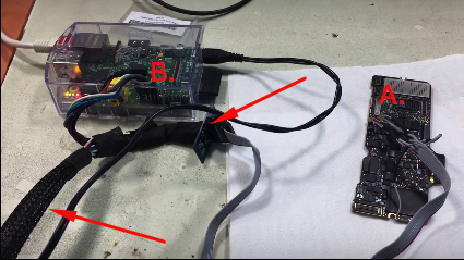
Thank you GhomsMaster, i think i have all the info to make some tests... In your successful video, can you explain us what things are where the arrows point ? It is supposed that the cables from point A (mac board) will go straight to the point B (raspberry). What this small circuit board is about ?
After i have weld the pins and i have connected to the raspberry, do i follow the guide 31-efi-removal-step-by-step ?? I have to read the bin file and i replace the EFI lock with FF. Do i need some extra files or something else ?
After i have weld the pins and i have connected to the raspberry, do i follow the guide 31-efi-removal-step-by-step ?? I have to read the bin file and i replace the EFI lock with FF. Do i need some extra files or something else ?
Last edit: 7 years 3 months ago by perarg.
Please Log in or Create an account to join the conversation.
- reverendalc
-
- Offline
- Haxor God
-
- This isn't Monaco... This is Baghdad
Less More
- Posts: 760
- Karma: 23
- Thank you received: 137
7 years 3 months ago #6048 by reverendalc
Replied by reverendalc on topic MacBook 12 A1534 EMC 2991
Yes after using the raspberry pi to read the EFI, you will manually remove the password from the bin and reflash.
If you are not well experienced with solder, I do recommend that you use temporary adhesive to make your connections. It's very easy to burn up your board, lift off pads, or otherwise destroy it.
If you are not well experienced with solder, I do recommend that you use temporary adhesive to make your connections. It's very easy to burn up your board, lift off pads, or otherwise destroy it.
The following user(s) said Thank You: perarg
Please Log in or Create an account to join the conversation.
7 years 3 months ago #6049 by perarg
Replied by perarg on topic MacBook 12 A1534 EMC 2991
Thank you reverendalc for the tips. I have experience with solder but a bad moment is always lurked I have to search in my country this adhesive, do you have any link to check about this so to have it as example and try to find just for an alternative to soldering ?
Please Log in or Create an account to join the conversation.
- reverendalc
-
- Offline
- Haxor God
-
- This isn't Monaco... This is Baghdad
Less More
- Posts: 760
- Karma: 23
- Thank you received: 137
7 years 3 months ago #6050 by reverendalc
Replied by reverendalc on topic MacBook 12 A1534 EMC 2991
www.amazon.com/Loctite-Fun-Tak-Mounting-2-Ounce-1087306/dp/B001F57ZPW
Solder wires to needles and tack the needles in place.
Solder wires to needles and tack the needles in place.
The following user(s) said Thank You: ChomsMaster, perarg
Please Log in or Create an account to join the conversation.
7 years 3 months ago - 7 years 3 months ago #6051 by perarg
Replied by perarg on topic MacBook 12 A1534 EMC 2991
It sounds clever this with needles. But i have to keep the needles straight up not contact with other elements of the board. It seems hard to me to keep eight needles straight with these tapes...
Last edit: 7 years 3 months ago by perarg. Reason: typo
Please Log in or Create an account to join the conversation.
- ChomsMaster
-
- Offline
- Script Kiddy
-
Less More
- Posts: 33
- Karma: 6
- Thank you received: 17
7 years 3 months ago #6052 by ChomsMaster
Replied by ChomsMaster on topic MacBook 12 A1534 EMC 2991
It is a simple connector that has my raspberry to solder bios chip and intercomunicar the clamp with the raspberry, you worry about soldering well or paste them correctly and that your raspberry is well configured, more of here I can not help you, it is already on your part do tests,
regards
regards
Please Log in or Create an account to join the conversation.
7 years 3 months ago #6079 by bestfood
Replied by bestfood on topic MacBook 12 A1534 EMC 2991
Does anyone know what chip it would be on this macbook 2016 12'
pi@raspberrypi:~ $ cd flashrom
pi@raspberrypi:~/flashrom $ sudo flashrom --p linux_spi:dev=/dev/spidev0.0
flashrom v0.9.9-unknown on Linux 4.4.21-v7+ (armv7l)
flashrom is free software, get the source code at flashrom.org
Calibrating delay loop... OK.
Found Macronix flash chip "MX25L6405" (8192 kB, SPI) on linux_spi.
Found Macronix flash chip "MX25L6405D" (8192 kB, SPI) on linux_spi.
Found Macronix flash chip "MX25L6406E/MX25L6408E" (8192 kB, SPI) on linux_spi.
Found Macronix flash chip "MX25L6436E/MX25L6445E/MX25L6465E/MX25L6473E" (8192 kB, SPI) on linux_spi.
Multiple flash chip definitions match the detected chip(s): "MX25L6405", "MX25L6405D", "MX25L6406E/MX25L6408E", "MX25L6436E/MX25L6445E/MX25L6465E/MX25L6473E"
Please specify which chip definition to use with the -c <chipname> option.
pi@raspberrypi:~/flashrom $
Please Log in or Create an account to join the conversation.
- ChomsMaster
-
- Offline
- Script Kiddy
-
Less More
- Posts: 33
- Karma: 6
- Thank you received: 17
7 years 3 months ago #6080 by ChomsMaster
Replied by ChomsMaster on topic MacBook 12 A1534 EMC 2991
@bestfood
Which EMC is the MacBook 12?
Which EMC is the MacBook 12?
Please Log in or Create an account to join the conversation.
7 years 3 months ago - 7 years 3 months ago #6081 by perarg
This is the same board as mine so this is EMC 2991
Replied by perarg on topic MacBook 12 A1534 EMC 2991
ChomsMaster wrote: @bestfood
Which EMC is the MacBook 12?
This is the same board as mine so this is EMC 2991
Last edit: 7 years 3 months ago by perarg.
Please Log in or Create an account to join the conversation.
7 years 3 months ago - 7 years 3 months ago #6082 by bestfood
Replied by bestfood on topic MacBook 12 A1534 EMC 2991
Yes it is, so do you know what macronix chip it would be?
Last edit: 7 years 3 months ago by bestfood.
Please Log in or Create an account to join the conversation.
- reverendalc
-
- Offline
- Haxor God
-
- This isn't Monaco... This is Baghdad
Less More
- Posts: 760
- Karma: 23
- Thank you received: 137
7 years 3 months ago #6085 by reverendalc
Replied by reverendalc on topic MacBook 12 A1534 EMC 2991
If memory serves me correctly its a winbond chip.
I'm not entirely sure it matters though, as pin assignments and SPI operations are identical through all models
I would use 6473e definition.
I'm not entirely sure it matters though, as pin assignments and SPI operations are identical through all models
I would use 6473e definition.
Please Log in or Create an account to join the conversation.
- ChomsMaster
-
- Offline
- Script Kiddy
-
Less More
- Posts: 33
- Karma: 6
- Thank you received: 17
7 years 3 months ago #6087 by ChomsMaster
Replied by ChomsMaster on topic MacBook 12 A1534 EMC 2991
It is not Macronix, the correct chip is a Winbond W25Q64FVBYIQ and in raspberry you have to use "W25Q64.V"
The following user(s) said Thank You: xzm1
Please Log in or Create an account to join the conversation.
Who's Online
We have 162 guests and no members online
N00BZ
- ljamal
- ljamal74
- mikeg2atest
- ducchinhbui
- anjarezt
Cookies
EU e-Privacy Directive
This website uses cookies to manage authentication, navigation, and other functions. By using our website, you agree that we can place these types of cookies on your device.
You have declined cookies. This decision can be reversed.
You have allowed cookies to be placed on your computer. This decision can be reversed.