Early 2011 MbPro EMC 2419 bad (no error) read bin
Rendering Error in layout Widget/Social: Call to a member function exists() on null. Please enable debug mode for more information.
If I helped you, buy me a beer!!! Happy Hunting...
Please Log in or Create an account to join the conversation.
- baileyw813
-
 Topic Author
 - Offline
- Script Kiddy
-

- Posts: 39
- Karma: 4
- Thank you received: 4
I gave up on this machine last night and I had a donor board (I also repair boards on the component level) with the same EMC/processor. I just removed the chip and placed the donor and all is well. I do have a couple other bare boards that are EFI password locked that I am still going to attempt to reprogram/flash.
**Made in PRC** assuming that is Peoples Republic of China... so I guess I "lucked" out on the PI system lol. Oh well. not sure if I can write the seller back and request a UK built model?
Please Log in or Create an account to join the conversation.
If I helped you, buy me a beer!!! Happy Hunting...
Please Log in or Create an account to join the conversation.
- baileyw813
- Topic Author
- Offline
- Script Kiddy
-
- Posts: 39
- Karma: 4
- Thank you received: 4
Please Log in or Create an account to join the conversation.

Please Log in or Create an account to join the conversation.
DeboTech wrote: I had a situation like this as well. What I did and I'm not sure it's the best solution. But I turned the computer on. I allowed it to run through the writing stage. All went well with the process. I know if anything is touched wrong there could be a shortage.
Just to add to this a bit, the reason this worked in your case was because the Mac needed power to something. What i mean is, the voltage was being drained from the pi somehow and the chip during read likey was failing or succeeding with a corrupt file. Supplying voltage to the board during the flashrom operation can remedy the situation.
Just for any of you reading this post, I do not think it wise to actually have the Mac powered on during the read/write process. And I think it is best to have pullup resistors on the 3.3v wires to be safe. The A1466 models are especially a pain in the rear when it comes to this process. Case in point; I have an A1466 that I fixed for a guy and he loaned it to me to help develop the MBA Easy FLash clips. I have not been able to reach this guy ever since HackMack.org went offline. So the battery finally drained on it as it was sitting in the corner. I grabbed it one day to test a batch of clips and couldn't get a good read to save my life! I threw it back in the corner as I was able to get the clips working on another Mac. I still haven't heard from the guy, so I decided to buy a SSD for it and use it. I am not going into detail of the nightmare I have had with this thing since, but I have a charger for it now and let it charge over night. After running into issues with installing OS X to the damned thing, I finally decided to try and pull the firmware and write another version back to it. I thought I was in for a ride, but I hooked it up to my pi and it read first try.
That long story just to tell you I had issues reading/writing one after letting the battery drain and when the battery was charged all my issues went away. Every mac is different so I think its best to start with no power and no charger connected to the logic board just to see if will read/write successfully, and then work your way up the latter by adding battery and then eventually the magsafe.
The whole point of this little sermon is to get through to you all that voltage stability while reeding any EEPROM is extremely important! Without having a steady and correctly applied voltage it will not work.
If I helped you, buy me a beer!!! Happy Hunting...
Please Log in or Create an account to join the conversation.
- baileyw813
- Topic Author
- Offline
- Script Kiddy
-
- Posts: 39
- Karma: 4
- Thank you received: 4
Please Log in or Create an account to join the conversation.
If I helped you buy me a latte!
Please Log in or Create an account to join the conversation.
- .::iRizwan::.
-

- Offline
- Haxor Guru
-

- One Machine can do the work of 50 ordinary men, No Machine can do the work of 1 extraordinary man
- Posts: 155
- Karma: 3
- Thank you received: 16
1. Remove the logic board from the body if possible. (to avoid short circuit etc..)
2. Attach the Charger (without battery if possible "some macs must need battery to be powered on") and power on the mac, wait atleast a minute (write protection to be disabled)
3. Now shut down the mac but let the charger attached.(Surely Powered)
4. then attach the soic clip or solder wires like i do and try to read write the chip.
5. You will be amazed.
I will be very happy if this helped someone else too.

if i helped you Buy me a Coffee
Please Log in or Create an account to join the conversation.
- baileyw813
- Topic Author
- Offline
- Script Kiddy
-
- Posts: 39
- Karma: 4
- Thank you received: 4
Please Log in or Create an account to join the conversation.
- baileyw813
- Topic Author
- Offline
- Script Kiddy
-
- Posts: 39
- Karma: 4
- Thank you received: 4
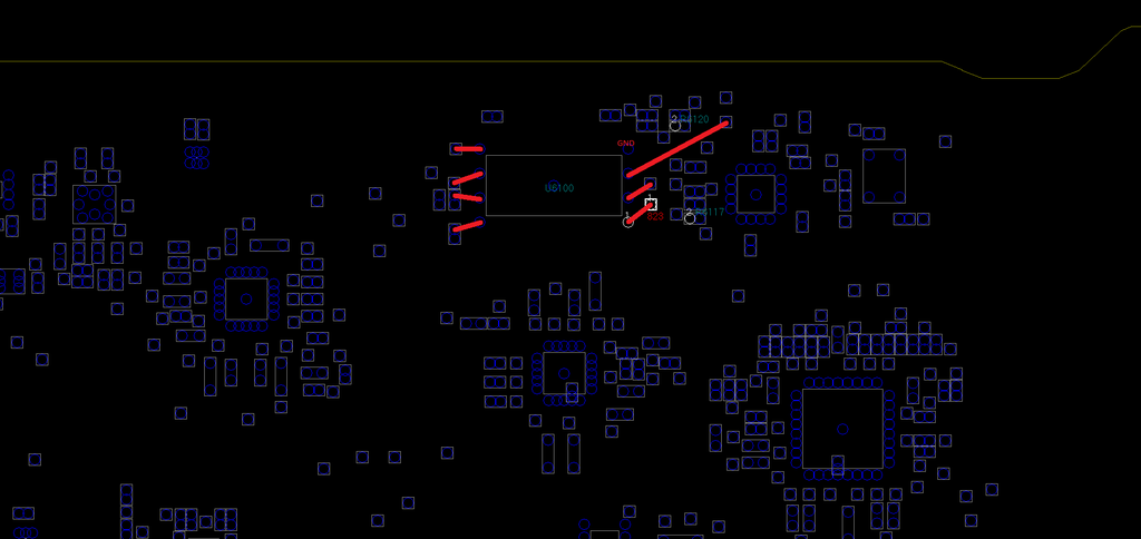
All the red lines from the U6100 (bios/EFI) chip are going to a spot on the board which has the same signal/continuity. So, soldering to that other point, is EXACTLY like soldering to the point on the chip the red line is leading to.
Please Log in or Create an account to join the conversation.
If I helped you buy me a latte!
Please Log in or Create an account to join the conversation.
- baileyw813
- Topic Author
- Offline
- Script Kiddy
-
- Posts: 39
- Karma: 4
- Thank you received: 4
IMO it would be wise to keep from soldering near any components if you are not experienced with soldering on these expensive boards (would help from avoiding ripping traces/legs off of the board.) So this could even help on machines like the 2011 MB Pro when you don't have a quality POMONA 5250 clip for the MX chips (instead of soldering right to the chip.)
Please Log in or Create an account to join the conversation.
- baileyw813
- Topic Author
- Offline
- Script Kiddy
-
- Posts: 39
- Karma: 4
- Thank you received: 4
not sure if this will help at all, but...
At first glance, this is what I have with the 2015 MacBook Air A1466 chip to header...
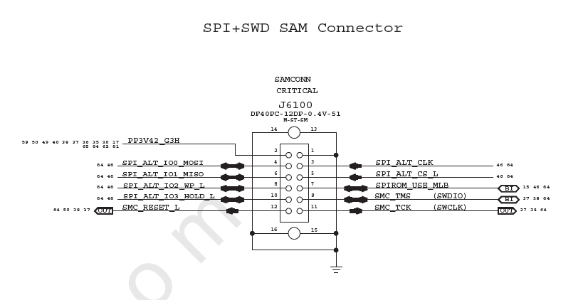
u6100
pin1 SPI_MLBROM_CS_L ---> PIN5
pin2 SPI_MLB_IO1_MISO --->PIN6
pin3 SPI_MLB_IO2_WP_L --->PIN8
pin4 GND --->GND (or PIN1, 13, 14, 15 or 16)
pin5 SPI_MLB_IO0_MOSI ---> PIN4
pin6 SPI_MLB_CLK---> TO PIN3
pin7 SPI_MLB_IO3_HOLD_L---> PIN10
pin8 PP3V3_SUS --> 3.3V
HEADER
PIN1 GND
PIN3 SPI_ALT_CLK
PIN4 SPI_ALT_IO0_MOSI
PIN5 SPI_ALT_CS_L
PIN6 SPI_ALT_IO1_MISO
PIN7 SPIROM_USE_MLB
PIN8 SPI_ALT_IO2_WP_L
PIN10 SPI_ALT_IO3_HOLD_L
PIN13 GND
PIN14 GND
PIN15 GND
PIN16 GND
Please Log in or Create an account to join the conversation.
If I helped you, buy me a beer!!! Happy Hunting...
Please Log in or Create an account to join the conversation.
If I helped you, buy me a beer!!! Happy Hunting...
Please Log in or Create an account to join the conversation.
baileyw813 wrote: This is what I had in mind. There are plenty of test points around the chip which would allow for an easier solder job. This isn't your exact board, but it is the 2014 A1466 820-3437-B. As long as you keep in mind the edge of the board, as well as the noted PIN 1, you'll be golden
All the red lines from the U6100 (bios/EFI) chip are going to a spot on the board which has the same signal/continuity. So, soldering to that other point, is EXACTLY like soldering to the point on the chip the red line is leading to.
This is extremely difficult for even myself to do at times. I have ruined a board soldering to the test point which was not fun. This is why I decided to manufacture a clip to interface with the board instead. I swear I will have a new project page up soon with the info on how to pre-order.
If I helped you, buy me a beer!!! Happy Hunting...
Please Log in or Create an account to join the conversation.
- baileyw813
- Topic Author
- Offline
- Script Kiddy
-
- Posts: 39
- Karma: 4
- Thank you received: 4
so very frustrating.
Side note, I am working on the mapping of all the boards I have access to (physically and through bv and schematics)
Please Log in or Create an account to join the conversation.
- baileyw813
- Topic Author
- Offline
- Script Kiddy
-
- Posts: 39
- Karma: 4
- Thank you received: 4
I wound up removing the efi chip from this computer and soldered one that I had on a VERY dead matching board with no efi/icloud and it works great.
However, it was still driving me crazy why I haven't been able to get a good read/just recently not even being able to detect chips.
I set it all up like I had before, however, this time I was able to find my old breadboard and hooked up PIN 17 (3.3V) to the breadboard and then pin 3,7,8 to the breadboard. I was having issues (still) with even detecting the chips on certain boards, BUT, the EFI chip (MX25L6408E) that was on the MB Pro that I could never get to read correctly, actually read just fine off of the logic board. I removed another chip (also the MX25L6408E) from another dead board and it wont read at all (not detected), so it could be a defective chip.
I've made some progress, at least I am able to detect the chips, but I am still getting bad reads or not detecting the chips at all.
I have a 2012 Mac Mini which it detects as the 25Q... chip without any "-c" operators, but it still gives me the bad read like I was having before.
This leads me to believe I may have a faulty SOIC8 clip (although it always reads that original chip now just fine, which I find to be VERY odd!!) I am going to order a new one, I wish I knew if Frys Electronics had these in stock, as I'd buy one from them a lot quicker...
Any way. sorry for the book. I will update more later. I just hate when someone doesn't keep in touch with issues/solutions in the end...
Please Log in or Create an account to join the conversation.
- baileyw813
- Topic Author
- Offline
- Script Kiddy
-
- Posts: 39
- Karma: 4
- Thank you received: 4
Yes... the shorter 10cm wires seemed to fix my voltage drop/loss issue. I am getting always between 3.29 and 3.3v and the clip/chip/board now.
Please Log in or Create an account to join the conversation.
Who's Online
We have 584 guests and no members online
N00BZ
- ljamal
- ljamal74
- mikeg2atest
- ducchinhbui
- anjarezt
Cookies
EU e-Privacy Directive
This website uses cookies to manage authentication, navigation, and other functions. By using our website, you agree that we can place these types of cookies on your device.
You have declined cookies. This decision can be reversed.
You have allowed cookies to be placed on your computer. This decision can be reversed.