- Posts: 760
- Karma: 23
- Thank you received: 137
Forum Login
Efi Removal Step-by-Step
Rendering Error in layout Widget/Social: Call to a member function exists() on null. Please enable debug mode for more information.
- reverendalc
-

- Offline
- Haxor God
-

- This isn't Monaco... This is Baghdad
Less More
7 years 6 months ago #4908 by reverendalc
Replied by reverendalc on topic Efi Removal Step-by-Step
Disconnect the battery and the MagSafe.
Put your multimeter on continuity.
Put one probe on leg 1 and visually follow the traces to the next test point or component, and test for continuity there. Once confirmed, take note or mark the point, then repeat with leg 2 through 8.
Put your multimeter on continuity.
Put one probe on leg 1 and visually follow the traces to the next test point or component, and test for continuity there. Once confirmed, take note or mark the point, then repeat with leg 2 through 8.
The following user(s) said Thank You: asterix99
Reply to reverendalc

7 years 6 months ago #4909 by k-pax
Replied by k-pax on topic Efi Removal Step-by-Step
hi,mariob what programmer is best tl866a or tl866cs?
I need buy,but I have rt809f
I need buy,but I have rt809f
Reply to k-pax
7 years 6 months ago #4911 by mariob
Friend, these are the exact points on the image above its logic board of each pin to be used in MiniPro TL866CS recorder!
Just identificar on your plate each point, and solder the wires.
Replied by mariob on topic Efi Removal Step-by-Step
asterix99 wrote: What's the best way to find the correct contact point on logic board where to solder the wires ?
Thanks
mariob wrote:
The following is an outline of its logic board, how to read your chip correctly!
You have to solder the wires to the correct points of its logic board, as it is in the picture!
Note. You will need to feed the wire pin 4 with GND, and the wire pin 8 with 3.3v!
Only then will have a correct reading.
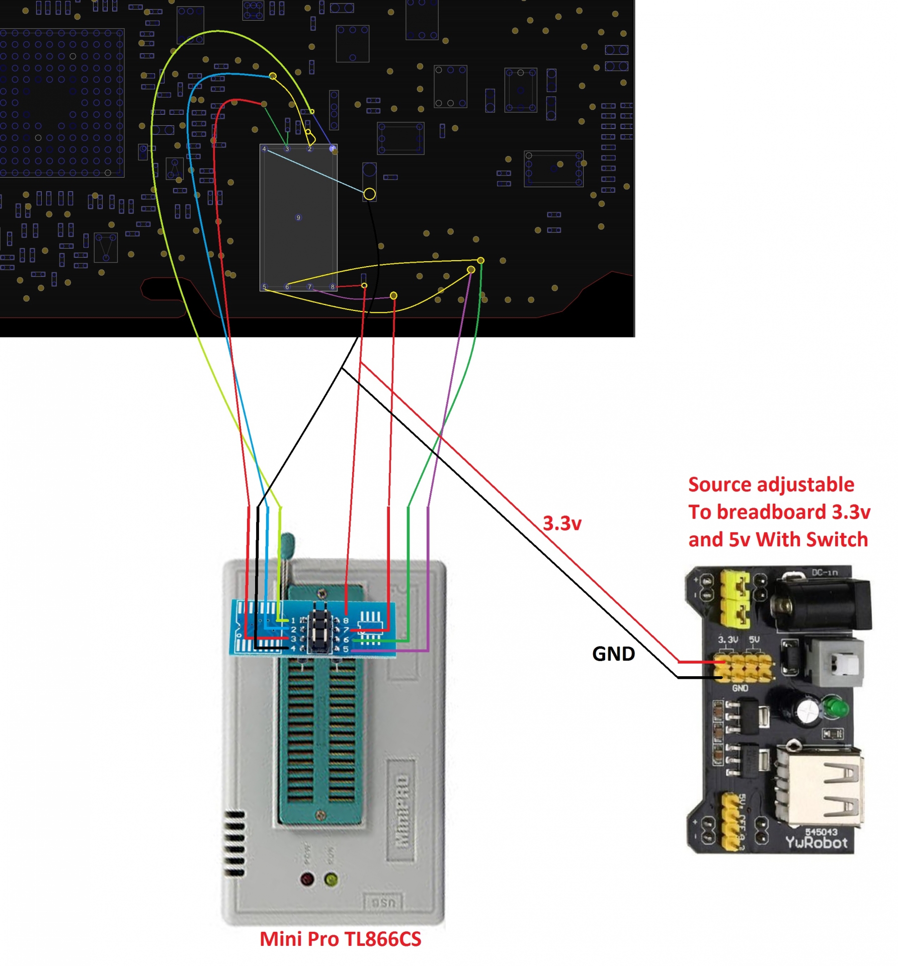
Friend, these are the exact points on the image above its logic board of each pin to be used in MiniPro TL866CS recorder!
Just identificar on your plate each point, and solder the wires.
Reply to mariob
7 years 6 months ago #4912 by mariob
Hello friend, all these writers are good, just knowing how to use properly to read the chip!
Never forget to use an external source to power the chip with 3.3v on pin 8, and pin 4 with GND!
In this way only will have success with your ROM.
Replied by mariob on topic Efi Removal Step-by-Step
k-pax wrote: hi,mariob what programmer is best tl866a or tl866cs?
I need buy,but I have rt809f
Hello friend, all these writers are good, just knowing how to use properly to read the chip!
Never forget to use an external source to power the chip with 3.3v on pin 8, and pin 4 with GND!
In this way only will have success with your ROM.
Reply to mariob
7 years 6 months ago #4914 by asterix99
If I not be wrong that voltage can be do by Raspberry 3 only.
Is it right?
Replied by asterix99 on topic Efi Removal Step-by-Step
Never forget to use an external source to power the chip with 3.3v on pin 8, and pin 4 with GND!
If I not be wrong that voltage can be do by Raspberry 3 only.
Is it right?
Reply to asterix99
- reverendalc
-
- Offline
- Haxor God
-
- This isn't Monaco... This is Baghdad
Less More
- Posts: 760
- Karma: 23
- Thank you received: 137
7 years 6 months ago #4915 by reverendalc
Replied by reverendalc on topic Efi Removal Step-by-Step
those programmers do not offer higher than 1.8v (mariob correct me if i'm wrong?)
you do not have to use the raspberry pi, you can use ANY 3.3v power supply with 3v3 and GND terminals. you could use an ATX power supply if you wanted.
but the 1.8v provided by the tl866 is not enough.
you do not have to use the raspberry pi, you can use ANY 3.3v power supply with 3v3 and GND terminals. you could use an ATX power supply if you wanted.
but the 1.8v provided by the tl866 is not enough.
Reply to reverendalc
7 years 6 months ago #4916 by mariob
Exactly my friend, recorders unfortunately not spend a load of 3.3V, an external source is needed for this, otherwise not consiguirá read the chip and successfully record!
Replied by mariob on topic Efi Removal Step-by-Step
reverendalc wrote: those programmers do not offer higher than 1.8v (mariob correct me if i'm wrong?)
you do not have to use the raspberry pi, you can use ANY 3.3v power supply with 3v3 and GND terminals. you could use an ATX power supply if you wanted.
but the 1.8v provided by the tl866 is not enough.
Exactly my friend, recorders unfortunately not spend a load of 3.3V, an external source is needed for this, otherwise not consiguirá read the chip and successfully record!
Reply to mariob
7 years 6 months ago #4917 by mariob
Hello friend, use the pins below the board for Raspberry PI:
PIN 8 + 7 + 3 together (3.3v, WP, HOLD) in PIN 17 Raspberry PI
PIN 5 MOSI in PIN 19 Raspberry PI
PIN 2 MISO in PIN 21 Raspberry PI
PIN 6 SCLK in PIN 23 Raspberry PI
PIN 4 GND in PIN 25 Raspberry PI
PIN 1 CS in PIN 24 Raspberry PI
But still may need an external source!
Replied by mariob on topic Efi Removal Step-by-Step
asterix99 wrote:
Never forget to use an external source to power the chip with 3.3v on pin 8, and pin 4 with GND!
If I not be wrong that voltage can be do by Raspberry 3 only.
Is it right?
Hello friend, use the pins below the board for Raspberry PI:
PIN 8 + 7 + 3 together (3.3v, WP, HOLD) in PIN 17 Raspberry PI
PIN 5 MOSI in PIN 19 Raspberry PI
PIN 2 MISO in PIN 21 Raspberry PI
PIN 6 SCLK in PIN 23 Raspberry PI
PIN 4 GND in PIN 25 Raspberry PI
PIN 1 CS in PIN 24 Raspberry PI
But still may need an external source!
The following user(s) said Thank You: asterix99
Reply to mariob
- reverendalc
-
- Offline
- Haxor God
-
- This isn't Monaco... This is Baghdad
Less More
- Posts: 760
- Karma: 23
- Thank you received: 137
7 years 6 months ago #4918 by reverendalc
Replied by reverendalc on topic Efi Removal Step-by-Step
If your raspberry pi is connected to a power supply of 5v1a or greater, you do not need an external power supply. That's the benefit of using the pi
The following user(s) said Thank You: asterix99
Reply to reverendalc
7 years 5 months ago - 7 years 5 months ago #4953 by asterix99
Replied by asterix99 on topic Efi Removal Step-by-Step
Hello,
now my logic board is on my desktop and I see the efi chip.... but how can you make that micro-solder ? Is very very small contacts ....any suggest ?
and by my multimeter I've difficult to find the pin5-contact, I've follow the images above but I can't find it. --> OK found it, is in the back of logic board!
The problem remain with micro solder that wires....
Thanks
now my logic board is on my desktop and I see the efi chip.... but how can you make that micro-solder
and by my multimeter I've difficult to find the pin5-contact, I've follow the images above but I can't find it. --> OK found it, is in the back of logic board!
The problem remain with micro solder that wires....
Thanks
Last edit: 7 years 5 months ago by asterix99.
Reply to asterix99
- reverendalc
-
- Offline
- Haxor God
-
- This isn't Monaco... This is Baghdad
Less More
- Posts: 760
- Karma: 23
- Thank you received: 137
7 years 5 months ago #4954 by reverendalc
Replied by reverendalc on topic Efi Removal Step-by-Step
for the very small contacts, you should use a soldering iron with a very fine tip. i've seen people attach sewing needles to soldering irons, though i'm not sure how well that works. a good micro tip is <$10.
for the wire, i would cut up a network cable or phone line and use the tiny wires inside.
strip the tip of the wire, tin it, then press it onto the contact with the iron.
perhaps you should dig up an old motherboard or something trivial to practice on
for the wire, i would cut up a network cable or phone line and use the tiny wires inside.
strip the tip of the wire, tin it, then press it onto the contact with the iron.
perhaps you should dig up an old motherboard or something trivial to practice on
The following user(s) said Thank You: asterix99
Reply to reverendalc
7 years 5 months ago #4955 by asterix99
Replied by asterix99 on topic Efi Removal Step-by-Step
Ok I'll check that way....
Reply to asterix99
7 years 5 months ago #4967 by asterix99
Replied by asterix99 on topic Efi Removal Step-by-Step
I'm try but It's very difficult, the contacts come off easily with the iron 
I think I need an easy flash connector. Can you help me about that ?
Thanks
I think I need an easy flash connector. Can you help me about that ?
Thanks
reverendalc wrote: for the very small contacts, you should use a soldering iron with a very fine tip. i've seen people attach sewing needles to soldering irons, though i'm not sure how well that works. a good micro tip is <$10.
for the wire, i would cut up a network cable or phone line and use the tiny wires inside.
strip the tip of the wire, tin it, then press it onto the contact with the iron.
perhaps you should dig up an old motherboard or something trivial to practice on
Reply to asterix99
- reverendalc
-
- Offline
- Haxor God
-
- This isn't Monaco... This is Baghdad
Less More
- Posts: 760
- Karma: 23
- Thank you received: 137
7 years 5 months ago #4968 by reverendalc
Replied by reverendalc on topic Efi Removal Step-by-Step
Connectors are released. Should be available for purchase shortly.
Keep an eye on the gh store
Keep an eye on the gh store
Reply to reverendalc
7 years 5 months ago - 7 years 5 months ago #4970 by asterix99
Replied by asterix99 on topic Efi Removal Step-by-Step
ok... in meantime I was reading here
ghostlyhaks.com/forum/efi-destroyer-lite/674-mac-reports-specifications-per-device the specifcs to find what connector is ok for my MAC Book Air A1465 EMC 2558 but I can't find my Mba model. What easy flash adapter is ok to use with my Raspberry PI 3 model b: 4.0.1, 4.0.2, 4.0.3 ?
Thanks
Thanks
Last edit: 7 years 5 months ago by asterix99.
Reply to asterix99
- reverendalc
-
- Offline
- Haxor God
-
- This isn't Monaco... This is Baghdad
Less More
- Posts: 760
- Karma: 23
- Thank you received: 137
7 years 5 months ago #4997 by reverendalc
Replied by reverendalc on topic Efi Removal Step-by-Step
you should be using 4.0.2
Reply to reverendalc
7 years 5 months ago #5000 by asterix99
Replied by asterix99 on topic Efi Removal Step-by-Step
Yes, I've check it already and purchased on 29/10 ")
Please can you say me if is it shipped ? n° GH021341016
Please can you say me if is it shipped
reverendalc wrote: you should be using 4.0.2
Reply to asterix99
7 years 4 months ago #5497 by asterix99
Replied by asterix99 on topic Efi Removal Step-by-Step
Hello,
when I use the connector Efi chip and Raspberry, need I to disconnect the battery pack of mac book before to start the flashroom process ?
when I use the connector Efi chip and Raspberry, need I to disconnect the battery pack of mac book before to start the flashroom process ?
Reply to asterix99
- reverendalc
-
- Offline
- Haxor God
-
- This isn't Monaco... This is Baghdad
Less More
- Posts: 760
- Karma: 23
- Thank you received: 137
7 years 4 months ago #5504 by reverendalc
Replied by reverendalc on topic Efi Removal Step-by-Step
your mileage may vary.
try:
battery disc, magsafe connected
battery AND magsafe connected
battery connected, magsafe disc
when you find your winning setup, please post results here:
ghostlyhaks.com/forum/efi-destroyer-lite/711-post-your-successful-flash-environments-here
try:
battery disc, magsafe connected
battery AND magsafe connected
battery connected, magsafe disc
when you find your winning setup, please post results here:
ghostlyhaks.com/forum/efi-destroyer-lite/711-post-your-successful-flash-environments-here
The following user(s) said Thank You: asterix99
Reply to reverendalc
7 years 4 months ago #5507 by asterix99
Replied by asterix99 on topic Efi Removal Step-by-Step
Thanks for reply, I've successfull disconnecting battery connector.
Now I've restarted with keys command+option+r+p and I've initialized the disk.
I've prepared an USB with el captain image... How can I start from usb to install the new OS ?
Thanks
Now I've restarted with keys command+option+r+p and I've initialized the disk.
I've prepared an USB with el captain image... How can I start from usb to install the new OS ?
Thanks
Reply to asterix99
Who's Online
We have 458 guests and no members online
N00BZ
- ljamal
- ljamal74
- mikeg2atest
- ducchinhbui
- anjarezt
Cookies
EU e-Privacy Directive
This website uses cookies to manage authentication, navigation, and other functions. By using our website, you agree that we can place these types of cookies on your device.
You have declined cookies. This decision can be reversed.
You have allowed cookies to be placed on your computer. This decision can be reversed.